


Controlling Color Difference in Anodized CNC Machining Parts: Definition, Causes, and Engineering Solutions
Why Color Difference Matters
For many customers of CNC machining parts, anodizing is a preferred finishing process. It improves corrosion resistance, surface hardness, and creates a clean metallic look.
But anodizing also brings one of the most common concerns: color difference.
👉 Customers often ask: “Why do two anodized parts look slightly different in shade, even if they come from the same order?”
The answer: color difference is normal in anodizing, but it can and should be controlled within an acceptable range.
What Is Color Difference?
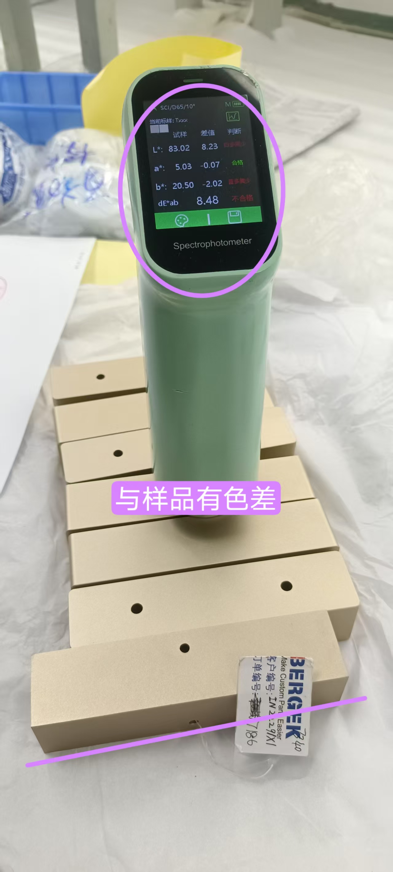
Color difference refers to the shade variation between anodized parts or batches. Instead of relying only on visual judgment, a spectrophotometer is used to measure a ΔE value:
ΔE < 1 → Usually invisible to the human eye
ΔE ≈ 1–3 → Slightly visible, generally acceptable for many applications
ΔE > 3 → Clearly visible, may be out of tolerance depending on the application
Acceptable ΔE Values in Different Applications
ΔE tolerance is not fixed; it depends on the end-use and customer requirements:
Functional / internal parts → ΔE ≤ 5 is often acceptable, as appearance is not critical.
Industrial housings / enclosures → ΔE ≤ 3–4 usually ensures visual consistency.
High-end consumer products (electronics, medical devices) → ΔE ≤ 1–2 is often required for strict cosmetic expectations.
Why Does Color Difference Occur?
Several factors contribute to color variation in anodizing.
1. Material-Related Factors
6061, 6063, 5052 → Stable, consistent anodizing results.
ADC12, A380 (die-cast alloys) → High silicon, prone to patchy or gray surfaces.
2024 (high copper) → More likely to show uneven or darker shades.
7075 (high strength, high Zn and Cu content) → Excellent strength but the oxide film is less uniform; dye absorption may vary, leading to more visible color differences.
• Industry consensus: The higher the alloy strength, the harder it is to control color variation. 2xxx and 7xxx alloys have higher shade difference risks compared with 5xxx/6xxx series.
• 6061/6063: Preferred for anodized appearance parts due to uniform structure and stable oxide film.
• 7075: Better suited for high-strength structural components, not cosmetic parts. If used for visible surfaces, confirm tolerance with the customer in advance and validate by sample.
• Recommended practice: Avoid mixing alloys in one assembly, keep material lots consistent, and always run anodizing tests on new material batches.
2. Pretreatment-Related Factors
Inconsistent degreasing or etching causes uneven surfaces.
Different surface finishes (polished, brushed, bead-blasted) create different shades even under the same anodizing process.
3. Process-Related Factors
Bath temperature fluctuations (beyond ±1 °C).
Current distribution differences from fixture design.
Electrolyte aging or contamination.
4. Assembly-Related Factors
Using different alloys in one design increases mismatch risk.
Producing parts in separate runs over long intervals adds variation.
5. Observation-Related Factors
Different light sources cause “metamerism” — parts may match under daylight but differ under LED.
Viewing angle and surface roughness affect perception.
How Bergek CNC Controls Color Difference
We do not promise “zero difference.” Instead, we ensure each batch stays within the agreed tolerance by applying methods suited to small-batch, multi-project production.
Material Consistency
Use the same alloy grade and lot for each order.
Maintain material certificates for traceability.
Stable Process Window
Bath temperature held within ±1 °C.
Current density and time strictly controlled.
Bath solutions refreshed based on analysis.
Standardized Inspection
Spectrophotometer used for first-article checks.
Comparison against customer-approved master samples under D65.
Selective record-keeping for projects where appearance is critical.
Reference Samples for Consistency
A physical reference sample is kept from the first approved run.
New batches are compared against this reference to ensure repeatability across orders.
Real Case Example
The root cause was traced to a new aluminum batch. After adjusting bath parameters and confirming against the client-approved reference sample, the ΔE values returned to within the defined range.
The client received visually consistent anodized parts, and the confirmed sample was retained as the standard for subsequent orders.
Final Thought
Color difference in anodizing is normal, measurable, and controllable. The key is to:
Define acceptable tolerance ranges with customers.
Apply objective measurement and controlled processes.
Retain reference samples to maintain consistency across repeat batches.
At Bergek CNC, we combine ISO 9001 quality systems, spectrophotometer checks, and CNC machining expertise to deliver anodized parts that are both functionally reliable and visually consistent, within realistic engineering limits.
Need support with anodizing or CNC machining projects?
Share your drawings or requirements with our engineering team. We will review your design, suggest suitable processes, and provide a tailored quotation.
FAQ: Common Questions About Anodizing Color Difference
Q1. Can anodizing colors be matched exactly to Pantone codes?
Pantone references are useful for indicating a general color direction, but anodized finishes cannot match Pantone shades exactly. Anodizing color depends on alloy composition, film thickness, dye type, and process conditions. The practical approach is to approve a physical sample and use it as the reference for future production.
Q2. Is the ΔE pass/fail threshold fixed?
No. The spectrophotometer measures ΔE values objectively, but the acceptance limit must be defined for each project. For example, industrial housings may allow ΔE ≤ 3–4, while consumer electronics may require ΔE ≤ 1–2. The tolerance should always be agreed upon in advance.
Q3. Why do parts from the same batch sometimes look different?
Factors such as fixture position, current distribution, surface finish, and alloy micro-variations can cause shade differences even within a single batch. Grouping visible parts together in the same run and using balanced fixturing reduces this effect.
Q4. How can consistency be maintained across repeat orders?
By keeping alloy lots consistent, controlling process parameters, and most importantly, retaining a master reference sample. Each new batch is compared against this sample to ensure visual consistency over time.
Q5. Does higher alloy strength always mean worse anodizing appearance?
In general, yes. High-strength alloys like 2xxx and 7xxx contain more copper and zinc, making the oxide film less uniform. This increases the risk of color variation. Alloys like 6061/6063 are more stable and are preferred for anodized appearance parts.


